
Engraving pens for writing and engraving on hardened steel, metal, glass, plastic, ceramic and stone
Mannesmann Demag engraving pen for manual engraving of various materials.
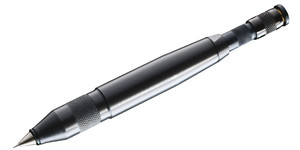
Engraving pen GST 540
Price on request

Engraving pen GST 540 M
Price on request
Engraving Pens for Writing and Engraving Hardened Steels, Metals, Glass, Plastics, Ceramics, and Stone
Engraving pens are precise tool solutions for permanent marking and fine-grained engraving on materials with high hardness and varying surface structures. In industrial manufacturing environments, they are used to apply component identifications, serial numbers, die markings, inspection features, and graphic forms directly into the material. Crucial factors include the choice of tip, the drive technology, and integration into clamping devices or automated systems. On this category page, you will find process explanations, selection criteria, installation instructions, and practical application scenarios for engraving pens in production, as well as information on compatibility and maintenance.
Functional Principle and Types
Engraving pens operate mechanically or electrically; common designs include pneumatic hammering pens, electromagnetically oscillating markers, and motor-driven rotary engraving pens. Mechanical impact pens create fine indentations through kinetic energy and are robust against heat-induced material changes when engraving hardened steel. Electromagnetic systems offer high frequencies and fine line guidance for inscriptions on thin-walled parts. Rotary engraving pens combine feed with a rotating tip and are popular for soft metals, plastics, and ceramics when material removal rather than deformation is desired. The tip typically consists of carbide (e.g., carbide head), diamond, or polycrystalline diamond (PCD) for abrasive materials such as glass or ceramic workpieces.
Material Compatibility and Tip Selection
For hardened steels (HRC > 40) and hard-milled components, carbide tips or PCD are the first choice. PCD tips deliver precise, clean edges with high wear resistance. For aluminum, copper, or soft steels, hardened steel tips or hardened tool steels may suffice. For glass, ceramics, and stone, diamond-sintered tips are required, as they abrade the material without creating micro-cracks, provided correct feed and rotation parameters are maintained. Plastics require a low penetration depth and often a lower feed rate to avoid tearing; here, sharp, finely ground tips are preferable. Plastic-coated or painted surfaces should be tested beforehand, as coating layers can chip or liquefy. When selecting, consider: hardness, brittleness, coating, surface roughness, and thermal sensitivity of the material.
Parameters: Impact Force, Frequency, Feed
Impact force and frequency determine the depth profile and contour sharpness. In pneumatic engraving pens, impact force is regulated via pressure (typically 4–8 bar) and throttling; for hardened steels, higher pressures and longer impacts are necessary, while glass and ceramics prefer higher impact frequencies with shallow impact depth. Electromagnetic pens operate in the range of several thousand strokes per minute with variable amplitude for fine control. Feed speed and feed direction must be synchronized with the impact frequency to achieve uniform lines without overlaps. In rotating systems, rotational speed (rpm) and feed (mm/min) are relevant parameters; high speeds with low feed rates reduce tearing in glass/stone.
Mechanical Interfaces, Mounting, and Integration
Engraving pens are mounted in tool holders, pneumatic cylinders, or robot flanges via standardized threads, piston mounts, or custom interfaces. Common mounting types include M6–M16 threads, cylindrical shafts with collet chucks, or flange connections for direct mounting. For robotic integration, rigid, play-free adapters and cable/air hose management are required to minimize signal latencies, vibrations, and abrasion. For CNC machines, electrical or pneumatic control lines synchronized with the machine control system are necessary. Pay attention to seals and protection systems when pens are used in cleaning or wet areas; high-quality O-rings (NBR, FKM) and protective caps extend service life and prevent the ingress of chips and coolants.
Maintenance, Wear, and Spare Parts
Tip wear is the most common wear pattern. Check tips for rounding, broken edges, and dimensional reduction at defined intervals. Documented replacement intervals are based on material and batch sizes; for serial marking of hardened steel, daily visual inspections are advisable, while for glass and ceramics, more frequent checks are sensible. Lubrication points in the impact mechanism require regular lubricant supply with suitable high-pressure greases; pneumatic pens benefit from oil-air cylinders with inline lubrication. Replacement tips and seal kits should be stocked as sets to minimize downtime. Spare part numbers and compatibility overviews can be found in the manufacturers' technical data sheets and in our product range.
Process Reliability, Marking Depth, and Readability
The required marking depth depends on inspection requirements, resistance to mechanical stress, and readability by visual or machine systems. For permanent readability on hardened steel, engraving depths of 0.1–0.5 mm are common; for contrast requirements, subsequent coloring or laser post-processing may be necessary. For machine reading (OCR, Datamatrix), character heights and line widths should be standardized; position tolerances can be maintained via reference marks and zero points in the clamping device. For heat-sensitive components, pay attention to the thermal effects of mechanical engravings; in such cases, solutions with smaller cutting areas or alternative marking methods should be considered.
Practical Examples
Example 1 — Serial marking of hardened shafts: A pneumatic engraving pen with a carbide tip is installed in a stationary clamping device. The workpiece is positioned via a stop, the pen operates at intervals with 6–8 bar pressure and 60–120 strokes/min, feed 5 mm/s, single marking depth 0.2 mm. The marking is done parallel to the axis for serial numbers and subsequently contrasted with black filling paste.
Example 2 — Engraving on glass signs: A diamond-tipped, rotating engraving pen operates at 20,000 rpm and low feed rates (50–200 mm/min). The glass surface is locally pre-stressed using a rubber pad to dampen vibrations. Fine lines are built up in several passes with low infeed to avoid tearing. After engraving, fine cleaning and optical quality control are performed.
Example 3 — PCB prototypes and plastic housings: An electromagnetic fine pen marks serial numbers on ABS housings without material breakthrough. The setting is done with high frequency and minimal amplitude, so that only the surface is marked and no structural weakening occurs. For PCBs, conductive fillers are avoided; instead, environmental parameters are chosen to prevent the formation of disturbing particles.
Selection Criteria at a Glance
- Material & hardness, desired engraving depth, production speed, integration interface (thread/flange), sealing and protection requirements
Integration into Production Lines
For automation, the electrical or pneumatic control of the engraving pen must be integrated into the line control. Use standardized interfaces such as 24V signals, digital IOs, or fieldbus modules. In multi-station layouts, trigger signals and reference encoders ensure synchronous marking. In robot cells, force/pressure sensors must also be installed to monitor contact forces and prevent tip breakage. For wet processing stations, shielded pens with corrosion-resistant seals and chip extraction are mandatory.
Documentation, Standards, and Compliance
Serial markings should be traceable and comply with common industry standards such as ISO 15614 (process documentation) or industry-specific requirements. For safety-relevant components, a test matrix with process parameters, test intervals, and spare parts lists is recommended. Manufacturers' technical data sheets provide reliable information on tip types, service life cycles, and recommended operating parameters. Further technical information and application examples can be found on our technology page https://maku-industrie.de/technik and in the specific practical examples under https://maku-industrie.de/anwendungsbeispiele.
Procurement and Configurator Information
Select engraving pens according to verified application parameters: material, batch sizes, intended cycle times, and existing interfaces. Order replacement tips, seal kits, and adapters together with the pen to minimize setup times. Use technical data sheets for final selection or contact our technical support with material samples and cycle specifications to obtain service life forecasts and optimal parameters.
FAQs
1. Which tip do I need for hardened steel?
For hardened steels, carbide or PCD tips are recommended. PCD offers higher wear resistance and longer service life for abrasive or very hard materials; carbide is cost-effective for moderate hardness. Check the specific hardness (HRC) and the desired engraving depth for the final decision.
2. Can an engraving pen be integrated into a robot cell?
Yes. Pay attention to rigid flange connections, coordinated air and cable routes, and control interfaces (24V, IO-Link, or fieldbus). Supplement the cell with force sensors and chip extraction to protect the tip and robot arm and ensure reproducible markings.
3. How do I extend the life of the tip?
Tip life can be extended by correct parameter selection (pressure, frequency, feed), regular visual inspection, clean clamping devices, suitable seals against chips/coolants, and stocking of replacement tips. For powdery or abrasive materials, diamond-tipped tips are the best investment in reduced downtime.