
Important Information from A to Z
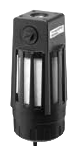
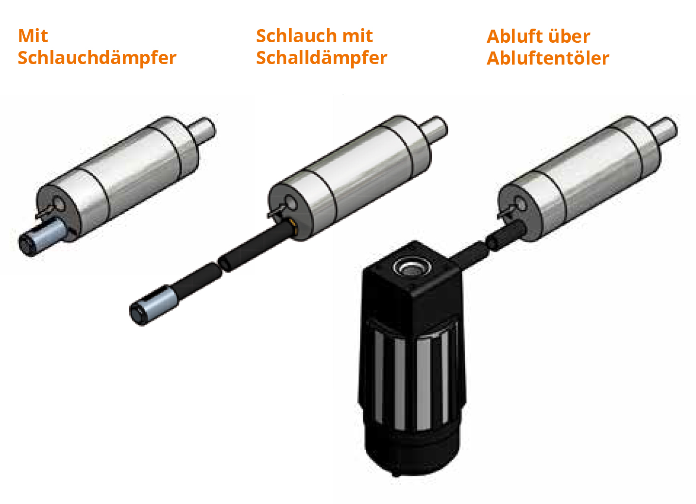
A pneumatic motor achieves an optimal service life when operated with oil. If oil mist is not desired at the point of use and the option of a long exhaust hose is not available, we recommend installing/attaching an exhaust air oil separator. The oil exiting the pneumatic motor with the exhaust air is guided into the exhaust air oil separator and collected (oil filtering up to 99 percent). Clean, unoiled air flows into the environment. Depending on the installation, noise reduction of up to 40 dB(A) is also achieved.
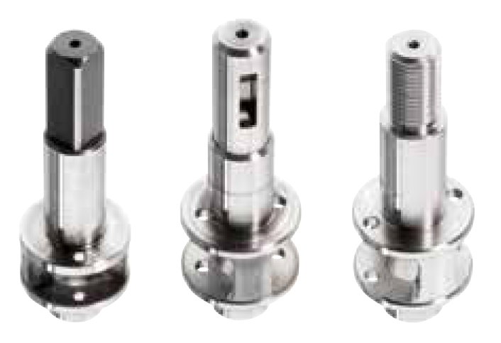
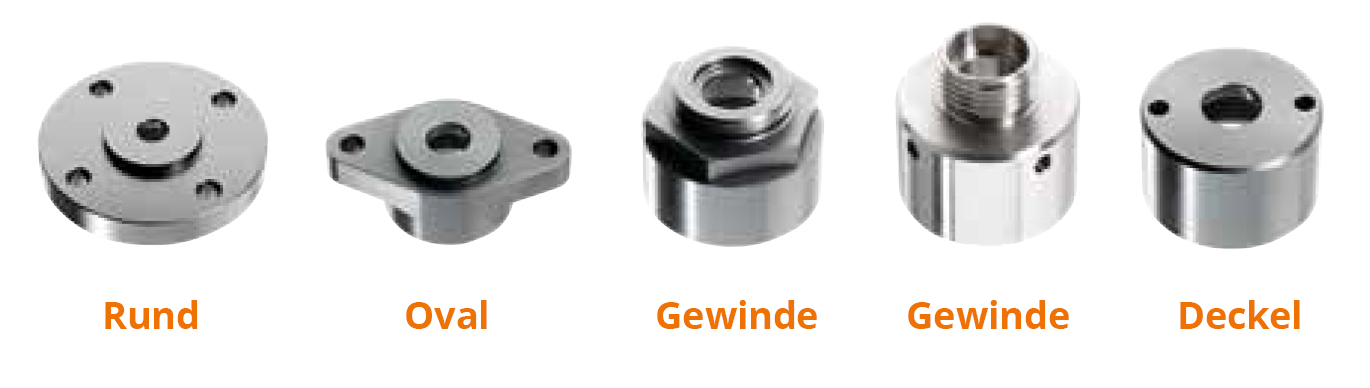
On request, various flange / output shaft variants such as bores, diameters, etc., are available according to your requirement profile.
Stall-proof motors can be operated up to the respective maximum torque. Once the maximum torque is reached, the pneumatic motor automatically comes to a standstill. This does not cause damage. If the pneumatic motor is brought to a standstill by a hard stop, high reaction torques occur. These can cause damage in continuous use.
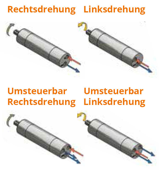
Clockwise Rotating Motors = Type MRD
Counter-Clockwise Rotating Motors = Type MLD
Torque and power are the same for both versions.
All clockwise rotating motors are also available in counter-clockwise rotating versions.
Reversible Motors = Type MUD
The respective compressed air line must be connected to the letters engraved at the air inlet
L = for Counter-Clockwise Rotation
R = for Clockwise Rotation
The pneumatic motors comply with the provisions of Directive 94/9/EC (ATEX) for equipment and protective systems intended for use in potentially explosive atmospheres.
The following Ex protection classes are available for the motors:
Zone 1 and 2 Gas Atmosphere II 2G c T5 –20 °C ≤ TA ≤ +40 °C
Zone 21 and 22 Dust Atmosphere II 2GD c IIC T4 D 135 ° –20 °C ≤ TA ≤ +50 °C
All performance data for the motors are based on an operating pressure of 6.3 bar. A reduction in operating pressure leads to a reduction in power. This can be used specifically in applications to perfectly adapt the motor to the conditions.
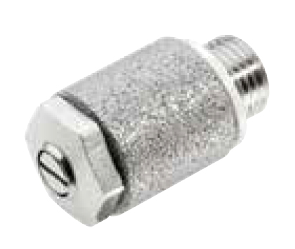
If the torque specified in the motor's technical data is required, but the speed needs to be reduced, the installation of a speed throttle is recommended. Installation is done via the exhaust air connection. The speed throttle is combined with a throttle valve and a silencer.
All performance data for the motors are based on an operating pressure of 6.3 bar. A reduction in operating pressure leads to a reduction in power. This can be used specifically in applications to perfectly adapt the motor to the conditions.
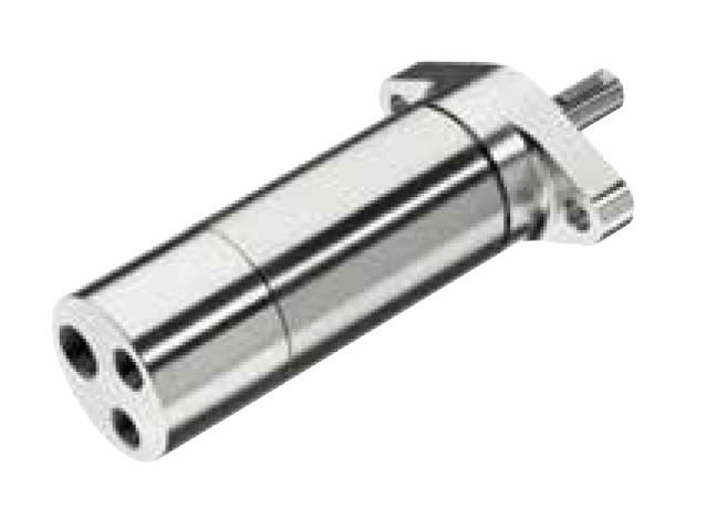
Stainless steel pneumatic motors are preferably used in the food and chemical industries. They are resistant to aggressive cleaning agents or corrosive air. All external parts are made of stainless steel.
The following steels are used:
Air inlet, housing, cover, flange, shaft output
X 10 Cr Ni S 18-9
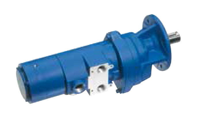
The motors of the MUB 23 series are equipped with a friction-locking holding brake. This is actuated directly with the supply air line of the pneumatic motor. No additional control line is required. The maximum holding force of the pneumatic motor's holding brake is equal to the starting torque.
The series MUB 300, 400 and 600 are equipped with a spring-loaded friction brake. The holding brake is controlled via a separate control line, which must be switched so that it releases earlier than the pneumatic motor receives working air. The control line of the holding brake must be released with at least 4.8 bar pressure (control line depressurised = holding brake engaged).
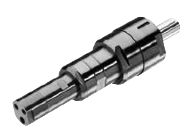
The motors equipped with high torques are standard motors of the respective series with an additional reduction gearbox. This achieves a high torque with a low speed. The air consumption is just as low as with a standard motor. The gearboxes are robust, have a high continuous output torque and can be used up to a standstill (stall torque).
These motors are designed for use with very slow speeds, in a small size and with low load torques. This maximum permissible torque must not be exceeded, as this can lead to damage to the motor. These motors are only specified with a no-load speed, as the speed remains approximately constant and does not drop below the maximum permissible torque.
The majority of pneumatic motors are available in an oil-free design. With completely dry compressed air, without any addition of oil, the no-load speed can drop depending on the running time of the pneumatic motor. If the compressed air contains oil, the functionality is not affected. The service life of the vanes even increases significantly. For shift work and continuous use, it is advisable to select and oil an oil-free pneumatic motor.
Non-oil-free pneumatic motors, on the other hand, must be oiled with approx. 2 – 3 drops of oil / minute. The excess oil can be filtered out via an exhaust air oil separator.
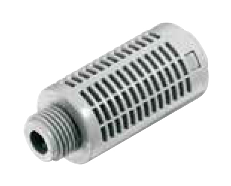
The mechanical running noises of a pneumatic motor are very minimal. Expanding exhaust air is primarily responsible for the noise generation in pneumatic motors. To reduce the exhaust air noise level dB(A), a silencer can be screwed into the exhaust air bore of the pneumatic motor series MRD and MUD. This is realised by a sintered disc in the pneumatic motor series MUB 23. The sound pressure level is therefore highly dependent on the type of silencing used and averages
77 dB(A) for pneumatic motors (0.11 – 1.2 kW).
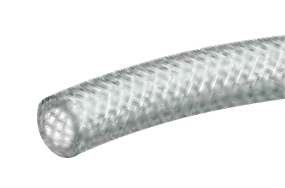
Information on recommended hose diameters can be found under the motor's technical data. The hose diameters are designed for a maximum hose length of 3 m. For supply air hose lengths exceeding 3 m, the resulting pressure drop must be considered, and a hose diameter of the next size may need to be selected.
Mannesmann Demag pneumatic motors are suitable for extreme operating conditions. Ambient temperatures from –30 °C to +100 °C and high humidity do not affect performance. There is a risk of icing at low temperatures due to the expanding exhaust air in the motor's exhaust area. However, these are harmless to the motor's operation. Specifically equipped motors can be supplied for particularly high ambient temperatures (up to 160 °C).
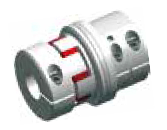
For use with non-stall-proof pneumatic motors, we recommend installing an overload clutch if there is a possibility in the application that the motors could be brought to a standstill while under pressure.
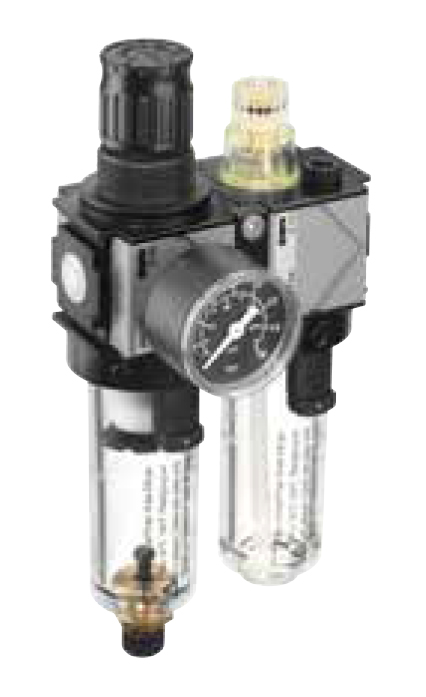
The reliability / service life of the pneumatic motor is ensured / extended by installing a service unit. The closer it is installed to the motor, the more efficient the effectiveness. If the service unit is more than 3 m away from the motor, it must be checked whether the pneumatic motor is supplied with sufficient oil due to the duty cycles.
Recommended: a service unit consisting of a compressed air regulator, mist lubricator, and water separator. However, it must be ensured that the flow cross-section (air flow rate) is at least as large as the air consumption of the motor.
As a rule, a 3/2 directional control valve is used for a non-reversible motor (types MRD…), and a 5/3 directional control valve is used for a reversible motor (types MUD…) for start-stop or change of direction of rotation. The flow rate should be designed so that the air flow rate is greater than the air consumption of the respective motor.
When connecting a reversible motor, it must be ensured that the non-actuated sides are vented. The air flow rate for venting must be at least twice the air consumption of the motor to prevent loss of performance (torque / speed).
Information on the maximum permissible shaft load can be found in the motor's technical data. If a higher load is required due to special requirements, this can be ensured by installing appropriate bearings. The permissible loads apply to vibration-free mounting of the motor. If the motor is subjected to vibrations and shocks, the axial load is greater and reduces the service life of the installed bearings.