
Order spring balancers, balancers and hose balancers
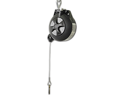
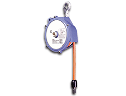
Spring Balancers, Balancers, and Hose Balancers: Technical Overview and Selection Criteria
Spring balancers and balancers are precision mechanical weight compensators that safely guide regularly used tools and hoses, neutralize their weight, and thus improve ergonomic operation and process reliability. In industrial environments, they reduce lifting and holding forces, prevent operator fatigue, and minimize shock and wear on connections. Hose balancers combine this function with flexible line systems for compressed air or hydraulics, while also enabling a defined operating radius and easy tool changes.
Construction and Materials
Spring balancers are based on internal tension springs with torsion bar-guided drums or plug-in mechanisms. Housings and support bodies are often made of galvanized steel, powder-coated sheet steel, or corrosion-resistant stainless steel. Steel cables made of galvanized wire or stainless steel wire ensure high breaking strength; plastic coatings reduce abrasion on lines. For hose balancers, high-quality high-pressure hoses made of NBR, HNBR, or polyamide are also used, depending on the medium and temperature range. Connection fittings are usually made of brass, stainless steel, or aluminum; seals consist of NBR, FKM (Viton), or EPDM, matched to the medium, temperature, and chemical resistance.
Designs and Drive Principles
There are three basic types: spring balancers with a simple return spring without locking, spring balancers with locking for tool-proximate positioning, and balancers with an internal force moment mechanism for continuous weight compensation. Mechanical locks operate via detents or click systems; hydraulic or damping elements integrate stop and end position damping. Hose balancers combine the spring balancer housing with an integrated hose reel or guide the hose protected externally along a slotted cable path.
Connections, Mounting, and Integration
Mounting points are standardized eyelets, hooks, or swivels with metric or fine-threaded fastenings. For repeatable positioning, a rotatable ceiling or wall mounting is useful; for mobile equipment, special brackets and quick couplings are recommended. Connection points for media require pressure-resistant quick couplings, plug connectors, or swivel joints with rotary seals. For compressed air hose balancers, two-stage quick couplings with overflow limitation are preferable to avoid leaks and pressure peaks.
Performance Spectrum, Selection, and Adjustment
Select spring balancers based on the static weight of the tool, dynamic forces during movement, and the desired working radius. Balancers are selected based on nominal compensating force (specified in Newtons or kilograms); correct dimensioning considers additional operating forces such as inertia or friction. Pay attention to adjustment ranges rather than just nominal values: many models allow fine adjustment in steps or continuously. For hose balancers, hose diameter, permissible operating pressure, and bending radius are also crucial, as excessively tight radii drastically reduce service life.
A compact checklist for selection:
- Tool weight + dynamic loads, working height and movement frequency; required compensation range and fine adjustability; connection type and seal compatibility; environmental conditions (humidity, temperature, corrosion); hose material, pressure class, and bending radius.
Sealing Technology and Maintenance
Seals are critical for continuous operation and safety: NBR is suitable for compressed air and general mineral oils, FKM for elevated temperatures and aggressive media, EPDM for water and some chemicals. Regular maintenance includes lubrication of guides, visual inspection of cables for corrosion or wire breakage, checking spring force, and functional tests of the locking mechanism. For hose balancers, additional checks of hose knots and fittings, as well as leak testing under operating pressure, are required. Replacement intervals depend on the number of cycles and environmental stress; document inspection cycles and spare part usage for audit and quality purposes.
Practical Examples
Example 1: Assembly workstation with pneumatic torque wrench. A spring balancer with locking supports the wrench, neutralizes its mass, and positions it ergonomically at eye level. The locking allows parallel placement during tool changes. Connection: quick coupling NW7.2 with swivel joint; seal: NBR for compressed air; housing: powder-coated steel. Result: reduced setup times, constant number of screwing cycles without operator fatigue.
Example 2: Conveyor belt feed with hose balancer for compressed air supply. Hose balancer with integrated polyamide hose DN6, operating pressure 10 bar, bending radius 60 mm. Mounted via swivel eyelet on a swivel arm construction, overpressure valve at the connection to prevent pressure peaks. Advantage: free movement along the belt length without hose wear, easy replacement of the hose line during maintenance.
Example 3: Assembly cell with balancer for pneumatic chisels. Balancer with continuous spring characteristic curve matched to changing tool weights between 3 and 7 kg, with integrated damping at the end position and stainless steel housing for splash water areas. Combined with swivel joint connection and FKM seals for increased temperature load. Result: controlled working forces, reduced wear on hose lines, improved process reliability.
Safety and Normative Requirements
Spring balancers and balancers must comply with relevant machine and occupational safety requirements. Pay attention to correctly dimensioned breaking load reserve (at least factor 7-12 depending on the application), CE conformity for integrated drive technology, and markings with load range and serial number for traceability. For applications with conductive media or spark formation, antistatic versions and additional grounding connections are required.
Integration into Occupational Safety and Quality System
Implement spring balancers into workplace analysis: record cycle data, wear indicators, and maintenance intervals in your maintenance plan. Use standardized test protocols to assess remaining service life and define replacement criteria (e.g., wire breakage >1/3 of the winding length, reduced spring force below tolerance). Documented test steps support audit processes and provide input for supplier audits.
Further technical information and specific application examples can be found at Technik and Anwendungsbeispiele.
FAQ
1. How do I dimension a spring balancer for a pneumatic tool?
Determine the static tool weight plus estimated dynamic additional load (inertial forces during acceleration). Select a spring balancer whose adjustment range covers the total weight. Consider friction losses and desired fine positioning; for frequent position changes, a version with locking or finely adjustable force is recommended. Check mounting height and arm geometry to ensure the spring balancer covers the entire working area.
2. Which hose materials are suitable for compressed air hose balancers?
For compressed air, polyamide hoses (PA) are common due to their low damping and abrasion resistance; NBR or HNBR hoses offer good flexibility and aging resistance. Select the material according to pressure class, temperature range, and chemical exposure. Pay attention to manufacturer specifications for the minimum bending radius to avoid kinking and premature wear.
3. What maintenance intervals are recommended?
Standard daily visual inspection before the start of the shift, functional and safety-relevant checks monthly, and a comprehensive inspection quarterly or after defined cycle counts. Replace worn cables and seals immediately; document all measures in the maintenance log. For increased loads (several thousand cycles/day, aggressive environment), significantly shorter intervals are required.